STM32F051R8T6

Features
• STM32F051R8T6
microcontroller featuring 64 KB Flash memory, 8 KB RAM in an LQFP64
package
• On-board
ST-LINK/V2 with selection mode switch to use the kit as a standalone
ST-LINK/V2 (with SWD connector for programming and debugging)
• Board power
supply: through USB bus or from an external 5 V supply voltage
• External
application power supply: 3 V and 5 V
• Voltage Range : 2.0 V to 3.6 V
• Four LEDs:
– LD1 (red) for
3.3 V power on
– LD2 (red/green)
for USB communication
– LD3 (green) for
PC9 output
– LD4 (blue) for
PC8 output
• Two push buttons
(user and reset)
• Extension header
for all LQFP64 I/Os for quick connection to prototyping board and
easy probing
• An additional
board is provided which can be connected to the extension connector
for even easier prototyping and probing.
• Comprehensive
free software in cluding a variety of examples, part of STM32CubeF0
package or STSW-STM32049 for legacy Standard Libraries usage
• 4 to 32 MHz Crystal Oscillator• Internal 8 MHz RC with x6 PLL Option
• Internal 40 kHz RC Oscillator
• Up to 55 Fast I/O
• 5-Channel DMA Controller
• One 12-bit D/A Converter
• Up to 11 timers
• 2 I2C
• 2 USARTs
• 2 SPIs
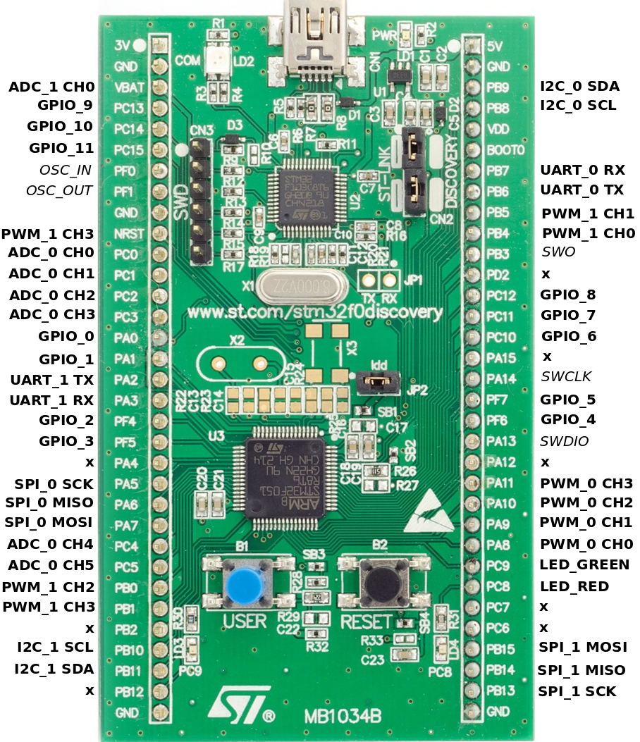
Board Pin Out
Software ที่ใช้ :
• STM32CubeMX
Download
here
• Keil
uVision4 (MDK4-ARM V4) Download
here

• ST-LINK/V2 Download
here ***สำหรับ Windows 8 จำเป็นต้องใช้ ST-Link ของ Windows 8***
ขั้นตอนการใช้งาน
แบ่งเป็น 2 ส่วน คือ
• ขั้นตอน Generate Project ด้วยโปรแกรม STM32CubeMX
• ขั้นตอนการเพิ่มโค้ด Blink ด้วยโปรแกรม Keil uVision4
ส่วนที่ 1 ขั้นตอน Generate Project ด้วยโปรแกรม STM32CubeMX
• เปิดโปรแกรม STM32CubeMx และ กดปุ่ม New
Project เพื่อสร้าง Project

• เลือกบอร์ดที่ต้องการใช้งาน

โดยในที่นี้ทางกลุ่มใช้งานบอร์ด STM32F051R8
ได้ทำการเลือก
• Vendor : STMicroelectronics
• Type of Board : Discovery
• MCU Series : STM32F0

• โปรแกรมก็ทำการ Filters บอร์ดที่ตรงกับที่ต้องการมาให้เลือก

• เลือก STM32F051R8 กดปุ่ม OK
ด้านล่างเพื่อให้โปรแกรมสร้าง Project
• หลังจากสร้าง Project แล้ว จะเห็นภาพตัวอย่าง MCU กับ Pin ที่ใช้งาน ซึ่งตัวโปรแกรมได้ทำการเปิดใช้งาน LED Pin : 8 และ 9 เป็น Output ให้แล้ว

• ทำการ Generate
โดยกดปุ่มเฟื่องที่เมนูด้านบน ทำการใส่ชื่อโปรเจค เลือก Toolchian/IDE : MDK-ARM
V4 แล้วกดปุ่ม OK โปรแกรมจะทำการ Generate Project เมื่อเสร็จสิ้นแล้วนั้นทำการกดปุ่ม Open Project เพื่อเริ่มใช้งาน
ส่วนที่ 2 ขั้นตอนการเพิ่มโค้ด Blink ด้วยโปรแกรม Keil
uVision4
• หลังจากกดปุ่ม Open Project ตัวโปรแกรม Keil uVision4 จะทำการเปิดโปรเจคที่ Generate ไว้ขึ้นมา

• ทำการคลิกโฟล์เดอร์ Application/User ในแถบทางซ้าย ดับเบิ้ลคลิกไฟล์ main.c เพื่อทำเพิ่มโค้ดไฟกระพริบ

• เพิ่มโค้ด
HAL_GPIO_TogglePin(GPIOC,
GPIO_PIN_9); //Toggle the state of pin PC9
HAL_Delay(100);
//delay 100ms

• ทำการกดปุ่ม Build หรือกดปุ่ม F7 เพื่อตรวจสอบ Path
Project และโค้กที่ทำการแก้ไข

• ตรวจสอบ Error ที่แถบ Build Output ด้านล่าง
• หลังจาก Build สำเร็จก็ทำการกดปุ่ม Download เพื่อ Flash code ไปยังบอร์ด STM32


**ปล. จากโค้ดข้างต้นจะทำให้ LED สีเขียวกระพริบ Pin9
แต่จากภาพเป็น LED สีฟ้ากระพริบ Pin8 **
No comments:
Post a Comment